
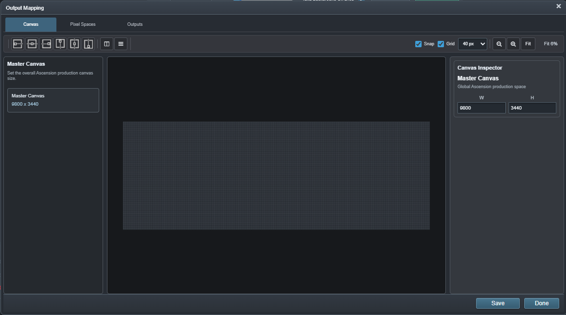
 01 · MASTER CANVAS
How large is the complete production stage?
The Master Canvas is the shared coordinate system for the event. It provides the overall stage dimensions in which every logical surface can be positioned.
STAGE + OUTPUT MAPPING
Ascension separates the production coordinate system, the logical surfaces in the show and the physical outputs that deliver those surfaces. Build the model once, then map real I/O underneath it.
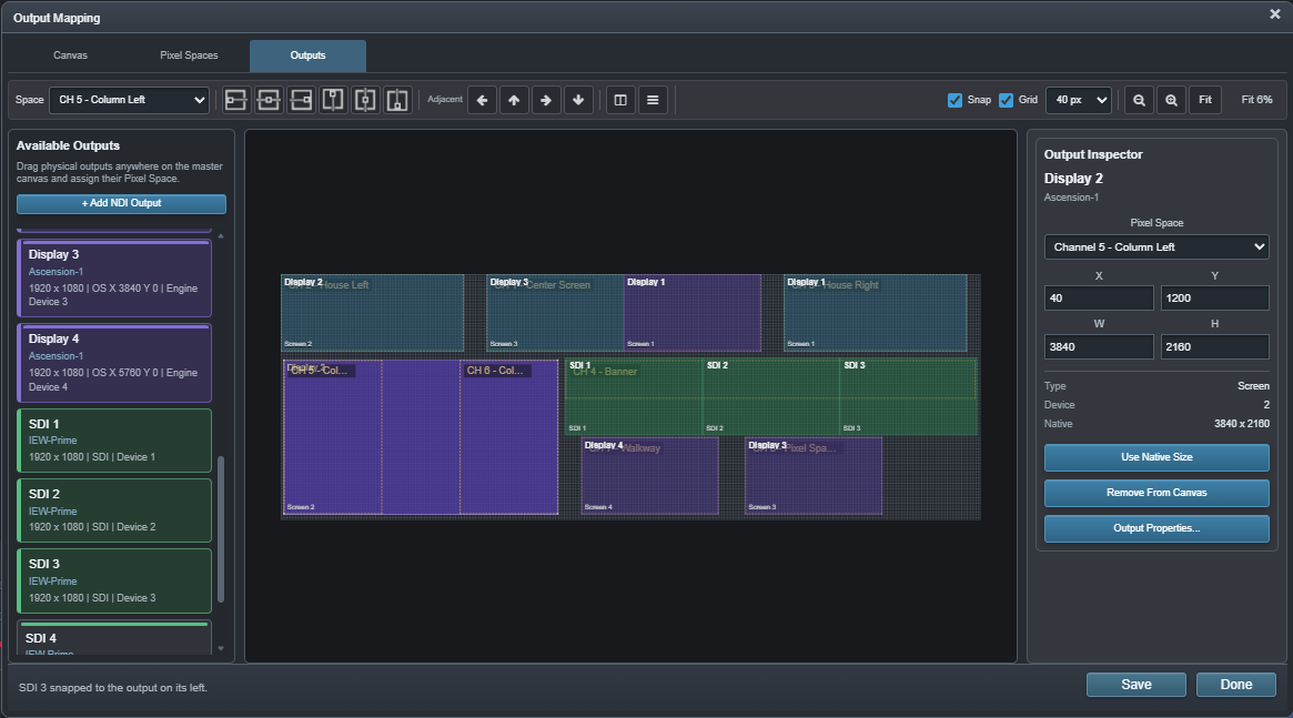
THREE LAYERS OF THE PHYSICAL SHOW
Each level answers a different question. Keeping those questions separate is what lets Ascension scale without forcing the programming model to mirror the cable plant.
01 · MASTER CANVASThe Master Canvas is the shared coordinate system for the event. It provides the overall stage dimensions in which every logical surface can be positioned.
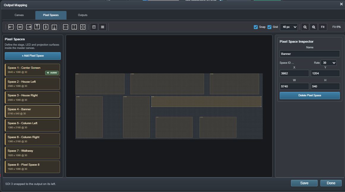 02 · PIXEL SPACES
Pixel Spaces define the actual stage surfaces the programming targets. Each one has a name, raster, position, engine channel and render rate.
03 · OUTPUTSPhysical outputs consume mapped regions of Pixel Spaces. Screen, DeckLink/SDI and NDI destinations can be assigned without turning those connectors into the identity of the show.
PIXEL SPACES
A stage rarely behaves like one rectangular monitor. Pixel Spaces let the event describe center screens, side surfaces, banners, scenic columns, floor or walkway canvases, projection areas and other logical destinations inside one larger production canvas.
PHYSICAL OUTPUTS
Output Mapping brings the available local and Extended-node I/O into one editor. Assign a physical output to the appropriate Pixel Space region and place it using the same stage coordinate system.
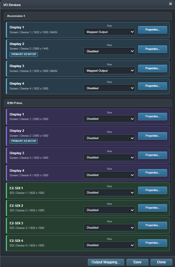
WHY THE SEPARATION MATTERS
The logical production remains stable while the physical implementation changes underneath it.
CueBoard rows, Timeline routes and layer states address logical Pixel Spaces instead of being built around specific display connectors.
Move a destination from one local display to another output or an Extended system without redesigning the creative stage model.
Extended nodes contribute physical I/O and rendering capacity to the same mapped production rather than creating another independently operated show.
REGISTRATION + TROUBLESHOOTING
Ascension's registration grid can target selected Pixel Spaces and generate continuous geometry that follows the logical stage model. That makes installation alignment and output-boundary troubleshooting part of the same workflow.
Explore monitoring and registration →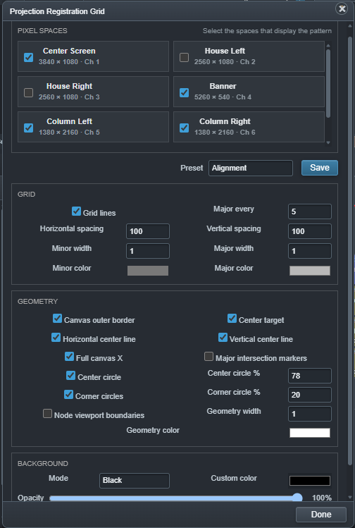
NEXT: DISTRIBUTE THE STAGE